WEARIFY

Simple Car Alarm Arming Horn Beep Canceller Project

This is the Simple Car Alarm Arming Horn Beep Canceller Circuit Diagram Project. It's a great convenience that most modern cars come with a built in alarm, however it is nothing but noise pollution that the horn sounds when the alarm is armed. Disconnecting the alarm system from the horn relay will eliminate this, but prevent the horn from sounding in the even of an actual alarm. This circuit serves to silence the arming beep yet maintain the alarm by introducing a small delay into the signal. 
 
Car Alarm Arming Horn Beep Canceller Circuit Diagram
 
Simple Car Alarm Arming Horn Beep Canceller Project


It sits between the alarm and horn relay. The alarm must provide a constant horn signal for at least 3 seconds before the horn relay is activated. That way the quick "beep" will never activate the horn relay, while the constant alarm signal will. 


Part           Total Qty.             Description
C1                   1           0.01uF Ceramic Disc Capacitor   
C2                   1           100uF 35V Electrolytic Capacitor   
R1                   1           1K 1/4W Resistor   
R2                   1           10K 1/4W Resistor   
R3                   1           15K 1/4W Resistor   
R4                   1           470 Ohm 1/4W Resistor   
D1, D3, D4      3           1N4004 Rectifier Diode   
D2                   1           Red LED   
U1                   1           555 Timer IC   
K1                   1           SPST 12V Automotive Relay   
MISC               1          Board, Wire, Socket For U1, Case   
Read More
WEARIFY

Glass Break Alarm Circuit Diagram

This circuit can be used for sounding an alarm to detect the breaking of a glass window by an intruder, even when the intruder ensures there is no sound of the shattered glass.
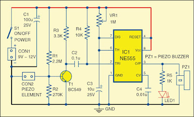
Fig. 1: Circuit of the glass break alarm

Circuit and working
  
Fig. 1 shows the circuit diagram of the glass break alarm. It is built around a piezo element connected across connector CON2, transistor BC549 (T1), timer NE555 (IC1), a piezo buzzer (PZ1) and a few other components.
A small piezo element used in the piezo buzzer is used as a sensor. It may be fixed at the centre of the window glass. IC1 is wired in monostable multivibrator mode, which is triggered by the piezo element. Output of IC1 is used to drive piezo buzzer PZ1. LED1 indicates the high-state output at pin 3 of IC1. Time delay can be adjusted by potentiometer VR1. Use an ordinary piezo buzzer at the output to generate a warning sound. This circuit works on 9V-12V DC.

When an intruder tries to break the glass, the piezo element generates an electric pulse, which is amplified and sent to the monostable multi-vibrator (IC1). The high output of IC1 drives LED1 and also produces a sound to indicate that someone is breaking the glass.

The 9V-12V DC power supply is connected across CON1, and the piezo element is connected across connector CON2.

Construction and testing
An actual-size, single-side PCB for the glass break alarm is shown in Fig. 2 and its component layout in Fig. 3. Enclose the PCB in a suitable small box in such a way that the piezo buzzer sounds when someone tries to break the glass window. Fix the piezo element at the centre of the window glass for best results.

Fig. 2: Actual-size PCB of the glass break alarm

Fig. 3: Component layout of the PCB


Use of 8-pin IC base is recommended for IC NE555.
Read More
WEARIFY

Simple Over Voltage Protector Circuit Diagram

This is the Simple Over Voltage Protector Circuit Diagram. The whole circuit of over voltage protector is build and fabricated around operational amplifier used as comparator. The inverting input is given to pin 2 of op-amp IC (IC1) with reference voltage of 5.1V from zener diode. Similarly, non-inverting input is given to pin no 3 of IC1 use as sensor for over voltage protector for sensing voltage fluctuation in the mains. The two transistors T1 and T2 conduct alternating (i.e. one at a time) according to the voltage of mains.

Simple Over Voltage Protector Circuit Diagram

Simple Over Voltage Protector Circuit Diagram


When voltage is around or below 240V AC transistor T1 is in off-state where T2 energized relay RL1. Similarly, when voltage becomes beyond 240V (i.e. above 240V) T1 is in conducting-stage and T2 is in off-stage which de-energized the relay RL1 and switch-off the appliance.

PARTS LIST

Resistors (all ¼-watt, ~+mn~ 5% Carbon)

R1 = 147 Ω/2W

R2 = 100 Ω/1W

R3 = 330 Ω

R4 = 100 KΩ

R5 = 1.8 KΩ

R6, R7 = 1 KΩ

VR1 = 10 KΩ

VR2 = 22 KΩ
Capacitors

C1, C4, C5 = 0.01 µF

C2 = 1000 µF/25V

C3 = 100 µF/25V
Semiconductors

IC1 = µA741 (Operational Amplifier)

IC2 = 7812

T1= BC547

T2 = SL100

D1, D2, D3, D4, D5 = 1N4007

D6 = 1N4148

ZD1 = 5.1V zener diode
Miscellaneous

X1 = 230V AC primary to 7.5V-0-7.5V, 1A secondary transformer

RL1 = 12V, 200Ω 1 C/O Relay

LED1 = RED
Read More
WEARIFY

A Handy Pen Torch Circuit Diagram

This easy to construct “Handy pen torch” electronic circuit and low component count, uses two power white LEDs for lighting. Low volt (4.8V dc) supply available from the built in rechargeable Ni-Cd battery pack is first converted into two channel (independent) constant current sources by two pieces of the renowned precision adjustable shunt regulator chip LM334 (IC1 and IC2). Around 25mA at 3.6 volt dc is available at the output of these ICs.

This regulated dc supply is used to drive two power white LEDs D4 and D6. Resistors R3 and R5 limits the output current (and hence the light output) of IC1 and IC2 circuits respectively. Besides these components, one red color LED (D2) is included in the main circuit which works as a battery charging supply input indicator. Resistor R1 limits the operating current of this LED.

Pen Torch Electronic Circuit Schematic

A Handy Pen Torch Circuit Diagram


Diode D1 works as an input polarity guard cum reverse current flow preventer. Capacitor C1 is a simple buffer for circuit stabilization. After succesful construction, preferably on a small piece of general purpose PCB, enclose the whole circuit in a suitable and attractive pen torch cabinet. If necessary, drill suitable holes in the cabinet to attatch the dc socket, on/off switch and the input indicator etc. In prototype,commonly available 4.8 volt/500mah Ni-Cd battery pack (for cordless telephones) is used.

One very simple but reliable ac mains powered battery charger circuit for the handy pen torch is also included here. Basically the pen torch circuit is a constant current charger wired around Transistor T1 (BC636), powered by a 12v/350mA step down transformer and associated componentsD1, D2 and C1.

AC mains powered battery charger for the pen torch


A Handy Pen Torch Circuit Diagram
Unregulated 12 volt dc available from the input power convereter circuit, comprising step down transformer(TRF), rectifier diodes (D1,D2) and filter capacitor (C1), is fed to T1 through a current limiting resistor R1. Grounded base PNP transistor T1 here works as a constant current generator. With 22 ohm resistor for R1, the charging current available at the output of the charger is near 50mA.

Red LED (D3) provides a fixed voltage reference to the base of T1, with the help of resistor R2. (During charging process, Diode D1 in the main circuit prevent reverse current flow from the battery pack when charging input supply is absent.) After construction of the pen torch circuit, fit the assembled unit inside a small plastic enclosure for safety and convenience.
Read More
WEARIFY

Automatic Dipper for Vehicles Project

While driving a car in night a problem like many drivers do not dip the head lamps of their vehicles in night while approaching. The several switching operation is used to dip the head light which may distract the concentration. To overcome this type of problem the innovative group Dreamlover Technology designs a unique electronics gadget called “Automatic Dipper” using very popular IC NE555 and LDR.

Circuit Description

The entire circuit of automatic dipper consist LDR followed by timer IC NE555 (IC1) and few other components, where LDR is used as sensor. LDR sense the light and change its internal resistance according light fall on it, which is further mounted in PVC pipe of 4 cm length positioned on the grill of car or in front such that the light fall on the LDR only when vehicles is approaching and is distance of 3M to 9M. When light fall on it the resistance decrease and makes output of IC1 low which energized the relay. The relay operates and voltage across the head lamps is reduced. When the distance between two approaching vehicles is more than 9 meter or less than 3 meter the circuit is not operated.

Automatic Dipper for Vehicles Circuit Diagram 

Automatic Dipper for Vehicles Project
 

The operating and non operating distance of the circuit can be varied by proper positioning of the PVC pipe and by adjusting the variable resistor VR1.


PARTS LIST
Resistors (all ¼-watt, ± 5% Carbon)

R1 = 10 Ω/10W

VR1 = 10 KΩ
Semiconductors

IC1 = NE555 (timer IC)

D1 = 1N4001
Miscellaneous

RL1 = 12V/100 Ω

LDR1= Light dependent resistor
Read More
WEARIFY

Electronic siren circuit Diagram

This is a compact electronic siren circuit based on three transistors.This circuit is suitable for in corporating with other alarm or siren projects such as burglar alarms, automatic factory sirens etc or a simple push to on alarm.

The  electronic siren circuit given here  is  based on a complementary transistor pair consisting of Q2 & Q3 (BC557 & BC 37)  wired as an astable multivibrator oscillator,which directly drives the speaker.The transistor Q1 is used to provide a full charge on capacitor C2 when power is turned ON. When push button switch S1 is pressed , the capacitor C2 slowly discharges through resistor R8.This makes the circuit to  oscillate at a low frequency that increases to a high frequency and kept indefinitely as the capacitor is fully discharged. When the switch P1 is released, the output  frequency decreases slowly as C2 is charged to the  positive voltage through resistance R6 and the Base-Emitter junction of tramsistor Q2. When C2 is fully charged to the positive battery voltage the  circuit stops oscillating.

Electronic siren circuit Diagram with Parts list.

Electronic siren circuit Diagram


Notes.


  • A 12 V battery or a a well regulated 12V DC power supply can be used to power the circuit.
  • Assemble the circuit on a good quality PCB or common board.
  • The switch S1 can be used to activate the alarm.
  • The switch S2 can be used as a power switch.
  • You can experiment on the tone of alarm by using different values for C2 and R8.
Read More
WEARIFY

Solar Powered SLA Battery Maintenance Schematic

This circuit was designed to ‘baby-sit’ SLA (sealed lead-acid or ‘gel’) batteries using freely available solar power. SLA batteries suffer from relatively high internal energy loss which is not normally a problem until you go on holidays and disconnect them from their trickle current charger. In some cases, the absence of trickle charging current may cause SLA batteries to go completely flat within a few weeks. The circuit shown here is intended to prevent this from happening. Two 3-volt solar panels, each shunted by a diode to bypass them when no electricity is generated, power a MAX762 step-up voltage converter IC.

Solar Powered SLA Battery Maintenance Circuit Diagram:

Solar Powered SLA Battery Maintenance Schematic

The ‘762 is the 15-volt-out version of the perhaps more familiar MAX761 (12 V out) and is used here to boost 6 V to 15 V.C1 and C2 are decoupling capacitors that suppress high and low frequency spurious components produced by the switch-mode regulator IC. Using Schottky diode D3, energy is stored in inductor L1 in the form of a magnetic field. When pin 7 of IC1 is open-circuited by the internal switching signal, the stored energy is diverted to the 15-volt output of the circuit. The V+ (sense) input of the MAX762, pin 8, is used to maintain the output voltage at 15 V. C4 and C5 serve to keep the ripple on the output voltage as small as possible. R1, LED D4 and pushbutton S1 allow you to check the presence of the 15-V output voltage.

D5 and D6 reduce the 15-volts to about 13.6 V which is a frequently quoted nominal standby trickle charging voltage for SLA batteries. This corresponds well with the IC’s maximum, internally limited, output current of about 120 mA. The value of inductor L1 is not critical — 22 µH or 47 µH will also work fine. The coil has to be rated at 1 A though in view of the peak current through it. The switching frequency is about 300 kHz. A suggestion for a practical coil is type M from the WEPD series supplied by Würth (www.we-online.com). Remarkably, Würth supply one-off inductors to individual customers. At the time of writing, it was possible, under certain conditions, to obtain samples, or order small quantities, of the MAX762 IC through the Maxim website at www.maxim-ic.com.
Read More
WEARIFY

Water Level Controller Detector

Water Level Controller Detector. In most houses, water is first stored in an underground tank (UGT) and from there it is pumped up to the overhead tank (OHT) located on the roof. People generally switch on the pump when their taps go dry and switch off the pump when the overhead tank starts overflowing. This results in the unnecessary wastage and sometimes non-availability of water in the case of emergency.  The simple circuit presented here makes this system automatic, i.e. it switches on the pump when the water level in the overhead tank goes low and switches it off as soon as the water level reaches a pre-determined level. It also prevents ‘dry run’ of the pump in case the level in the underground tank goes below the suction level. 

Water Level Controller Detector

 
In the figure, the common probes connecting the underground tank and the overhead tank to +9V supply are marked ‘C’. The other probe in underground tank, which is slightly above the ‘dry run’ level, is marked ‘S’. The low-level and high-level probes in the overhead tank are marked ‘L’ and ‘H’, respectively.  When there is enough water in the underground tank, probes C and S are connected through water.As a result,transistor T1 gets forward biased and starts conducting. This, in turn, switches transistor T2 on. 

Initially, when the overhead tank is empty, transistors T3 and T5 are in cut-off state and hence pnp transistors T4 and T6 get forward biased via resistors R5 and R6, respectively.  As all series-connected transistors T2, T4, and T6 are forward biased, they conduct to energise relay RL1 (which is also connected in series with transistors T2, T4, and T6). Thus the supply to the pump motor gets completed via the lower set of relay contacts (assuming that switch S2 is on) and the pump starts filling the overhead tank. 
Controller Detector
Once the relay has energised, transistor T6 is bypassed via the upper set of contacts of the relay. As soon as the water level touches probe L in the overhead tank, transistor T5 gets forward biased and starts conducting. This, in turn, reverse biases transistor T6, which then cuts off. But since transistor T6 is bypassed through the relay contacts, the pump continues to run. The level of water continues to rise.  When the water level touches probe H, transistor T3 gets forward biased and starts conducting. This causes reverse biasing of transistor T4 and it gets cut off. As a result, the relay de-energises and the pump stops. Transistors T4 and T6 will be turned on again only when the water level drops below the position of L probe. 

Presets VR1, VR2, and VR3 are to be adjusted in such a way that transistors T1, T3, and T5 are turned on when the water level touches probe pairs C-S, C-H, and C-L, respectively. Resistor R4 ensures that transistor T2 is ‘off’ in the absence of any base voltage. Similarly, resistors R5 and R6 ensure that transistors T4 and T6 are ‘on’ in the absence of any base voltage. Switches S1 and S2 can be used to switch on and switch off, respectively, the pump manually.  You can make and install probes on your own as per the requirement and facilities available. However, we are describing here how the probes were made for this prototype. 

The author used a piece of non-metallic conduit pipe (generally used for domestic wiring) slightly longer than the depth of the overhead tank. The common wire C goes up to the end of the pipe through the conduit. The wire for probes L and H goes along with the conduit from the outside and enters the conduit through two small holes bored into it as shown in Fig. 2. Care has to be taken to ensure that probes H and L do not touch wire C directly. Insulation of wires is to be removed from the points shown. The same arrangement can be followed for the underground tank also. To avoid any false triggering due to interference, a shielded wire may be used.
Read More