Showing posts with label LED Flasher. Show all posts
WEARIFY

Reliable Car Battery Tester Circuit Diagram

Reliable Car Battery Tester Circuit Diagram

This circuit uses the popular and easy to find LM3914 IC. This IC is very simple to drive, needs no voltage regulators (it has a built in voltage regulator) and can be powered from almost every source. This circuit is very easy to explain: When the test button is pressed, the Car battery voltage is feed into a high impedance voltage divider. His purpose is to divide 12V to 1,25V (or lower values to lower values).

This solution is better than letting the internal voltage regulator set the 12V sample voltage to be feed into the internal voltage divider simply because it cannot regulate 12V when the voltage drops lower (linear regulators only step down). Simply wiring with no adjust, the regulator provides stable 1,25V which is fed into the precision internal resistor cascade to generate sample voltages for the internal comparators. Anyway the default setting let you to measure voltages between 8 and 12V but you can measure even from 0V to 12V setting the offset trimmer to 0 (but i think that under 9 volt your car would not start).

There is a smoothing capacitor (4700uF 16V) it is used to adsorb EMF noise produced from the ignition coil if you are measuring the battery during the engine working. Diesel engines would not need it, but I'm not sure. If you like more a point graph rather than a bar graph simply disconnect pin 9 on the IC (MODE) from power. The calculations are simple (default)

For the first comparator the voltage is : 0,833 V corresponding to 8 V
* * * * * voltage is : 0,875 V corresponding to 8,4 V
for the last comparator the voltage is : 1,25 V corresponding to 12 V
Have fun, learn and don't let you car battery discharge... ;-)
Read More
WEARIFY

MT8870 DTMF Telephone Dial Tone Decoder Circuit Diagram

Build a MT8870 DTMF Telephone Dial Tone Decoder Circuit Diagram. This is a  simple MT8870 DTMF Telephone Dial Tone Decoder Circuit Diagram. In this circuit one common DTMF receiver IC is the Motorola MT8870 that is widely used in electronic communications circuits. The MT8870 isan 18-pin IC. It is used in telephones and a variety of other applications. When a proper output is not obtained in projects using this IC, engineers or technicians need to test this IC separately. 

A quick testing of this IC could save a lot of time in research labs and manufacturing industries of communication instruments. Here’s a small and handy tester circuit for the DTMF IC. It can be assembled on a multipurpose PCB with an 18-pin IC base. One can also test the IC on a simple breadboard. For optimum working of telephone equipment, the DTMF receiver must be designed to recognize a valid tone pair greater than 40 ms in duration and to accept successive digit tone-pairs that are greater than 40 ms apart. 

 MT8870 DTMF Telephone Dial Tone Decoder Circuit Diagram

MT8870 DTMF Telephone Dial Tone Decoder Circuit Diagram

Read More
WEARIFY

Automatic Headlight Brightness Switch Project

Driving the highway with your high-beam headlights can really increase your visibility, but can be a blinding hazard for other drivers. This simple circuit can be wired into your headlight switch to provide automatic switching between high and low beam headlights when there is oncoming traffic. It does this by sensing the lights of that traffic. In this way, you can drive safely with your high-beams on without blinding other drivers.

Automatic Headlight Brightness Switch Circuit Diagram

Automatic Headlight Brightness Switch Project


Parts

Part    Total Qty    Description
R1              1         5K 1/4W Resistor   
R2,R3,R4   3         5K Pot   
Q1              1         NPN Phototransistor   
Q2              1         2N3906 PNP Transistor   
K1              1         Low Current 12V SPST Relay   
K2              1         High Current 12V SPDT Relay   
S1               1         SPST Switch   
B1               1         Car Battery   
MISC          1         Case, wire, board, knobs for pots   

Notes

Q1 should me mounted in such a way so it points toward the front of the car with a clear line of site. Suitable places are on the dashboard, in the front grill, etc.
Adjust all the pots for proper response by testing on a deserted road.
S1 enables and disables the circuit.
B1 is, obviously, in the car already.
Before you try to connect this circuit, get a wiring diagram for your car. Some auto manufacturers do weird things with wiring.
Connection A goes to the high beam circuit, B goes to the headlight switch common and C connects to the low beam circuit.
Read More
WEARIFY

Glass Break Alarm Circuit Diagram

This circuit can be used for sounding an alarm to detect the breaking of a glass window by an intruder, even when the intruder ensures there is no sound of the shattered glass.
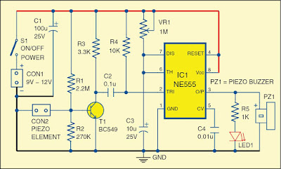
Fig. 1: Circuit of the glass break alarm

Circuit and working
  
Fig. 1 shows the circuit diagram of the glass break alarm. It is built around a piezo element connected across connector CON2, transistor BC549 (T1), timer NE555 (IC1), a piezo buzzer (PZ1) and a few other components.
A small piezo element used in the piezo buzzer is used as a sensor. It may be fixed at the centre of the window glass. IC1 is wired in monostable multivibrator mode, which is triggered by the piezo element. Output of IC1 is used to drive piezo buzzer PZ1. LED1 indicates the high-state output at pin 3 of IC1. Time delay can be adjusted by potentiometer VR1. Use an ordinary piezo buzzer at the output to generate a warning sound. This circuit works on 9V-12V DC.

When an intruder tries to break the glass, the piezo element generates an electric pulse, which is amplified and sent to the monostable multi-vibrator (IC1). The high output of IC1 drives LED1 and also produces a sound to indicate that someone is breaking the glass.

The 9V-12V DC power supply is connected across CON1, and the piezo element is connected across connector CON2.

Construction and testing
An actual-size, single-side PCB for the glass break alarm is shown in Fig. 2 and its component layout in Fig. 3. Enclose the PCB in a suitable small box in such a way that the piezo buzzer sounds when someone tries to break the glass window. Fix the piezo element at the centre of the window glass for best results.

Fig. 2: Actual-size PCB of the glass break alarm

Fig. 3: Component layout of the PCB


Use of 8-pin IC base is recommended for IC NE555.
Read More
WEARIFY

Simple Over Voltage Protector Circuit Diagram

This is the Simple Over Voltage Protector Circuit Diagram. The whole circuit of over voltage protector is build and fabricated around operational amplifier used as comparator. The inverting input is given to pin 2 of op-amp IC (IC1) with reference voltage of 5.1V from zener diode. Similarly, non-inverting input is given to pin no 3 of IC1 use as sensor for over voltage protector for sensing voltage fluctuation in the mains. The two transistors T1 and T2 conduct alternating (i.e. one at a time) according to the voltage of mains.

Simple Over Voltage Protector Circuit Diagram

Simple Over Voltage Protector Circuit Diagram


When voltage is around or below 240V AC transistor T1 is in off-state where T2 energized relay RL1. Similarly, when voltage becomes beyond 240V (i.e. above 240V) T1 is in conducting-stage and T2 is in off-stage which de-energized the relay RL1 and switch-off the appliance.

PARTS LIST

Resistors (all ¼-watt, ~+mn~ 5% Carbon)

R1 = 147 Ω/2W

R2 = 100 Ω/1W

R3 = 330 Ω

R4 = 100 KΩ

R5 = 1.8 KΩ

R6, R7 = 1 KΩ

VR1 = 10 KΩ

VR2 = 22 KΩ
Capacitors

C1, C4, C5 = 0.01 µF

C2 = 1000 µF/25V

C3 = 100 µF/25V
Semiconductors

IC1 = µA741 (Operational Amplifier)

IC2 = 7812

T1= BC547

T2 = SL100

D1, D2, D3, D4, D5 = 1N4007

D6 = 1N4148

ZD1 = 5.1V zener diode
Miscellaneous

X1 = 230V AC primary to 7.5V-0-7.5V, 1A secondary transformer

RL1 = 12V, 200Ω 1 C/O Relay

LED1 = RED
Read More
WEARIFY

A Handy Pen Torch Circuit Diagram

This easy to construct “Handy pen torch” electronic circuit and low component count, uses two power white LEDs for lighting. Low volt (4.8V dc) supply available from the built in rechargeable Ni-Cd battery pack is first converted into two channel (independent) constant current sources by two pieces of the renowned precision adjustable shunt regulator chip LM334 (IC1 and IC2). Around 25mA at 3.6 volt dc is available at the output of these ICs.

This regulated dc supply is used to drive two power white LEDs D4 and D6. Resistors R3 and R5 limits the output current (and hence the light output) of IC1 and IC2 circuits respectively. Besides these components, one red color LED (D2) is included in the main circuit which works as a battery charging supply input indicator. Resistor R1 limits the operating current of this LED.

Pen Torch Electronic Circuit Schematic

A Handy Pen Torch Circuit Diagram


Diode D1 works as an input polarity guard cum reverse current flow preventer. Capacitor C1 is a simple buffer for circuit stabilization. After succesful construction, preferably on a small piece of general purpose PCB, enclose the whole circuit in a suitable and attractive pen torch cabinet. If necessary, drill suitable holes in the cabinet to attatch the dc socket, on/off switch and the input indicator etc. In prototype,commonly available 4.8 volt/500mah Ni-Cd battery pack (for cordless telephones) is used.

One very simple but reliable ac mains powered battery charger circuit for the handy pen torch is also included here. Basically the pen torch circuit is a constant current charger wired around Transistor T1 (BC636), powered by a 12v/350mA step down transformer and associated componentsD1, D2 and C1.

AC mains powered battery charger for the pen torch


A Handy Pen Torch Circuit Diagram
Unregulated 12 volt dc available from the input power convereter circuit, comprising step down transformer(TRF), rectifier diodes (D1,D2) and filter capacitor (C1), is fed to T1 through a current limiting resistor R1. Grounded base PNP transistor T1 here works as a constant current generator. With 22 ohm resistor for R1, the charging current available at the output of the charger is near 50mA.

Red LED (D3) provides a fixed voltage reference to the base of T1, with the help of resistor R2. (During charging process, Diode D1 in the main circuit prevent reverse current flow from the battery pack when charging input supply is absent.) After construction of the pen torch circuit, fit the assembled unit inside a small plastic enclosure for safety and convenience.
Read More
WEARIFY

Electronic siren circuit Diagram

This is a compact electronic siren circuit based on three transistors.This circuit is suitable for in corporating with other alarm or siren projects such as burglar alarms, automatic factory sirens etc or a simple push to on alarm.

The  electronic siren circuit given here  is  based on a complementary transistor pair consisting of Q2 & Q3 (BC557 & BC 37)  wired as an astable multivibrator oscillator,which directly drives the speaker.The transistor Q1 is used to provide a full charge on capacitor C2 when power is turned ON. When push button switch S1 is pressed , the capacitor C2 slowly discharges through resistor R8.This makes the circuit to  oscillate at a low frequency that increases to a high frequency and kept indefinitely as the capacitor is fully discharged. When the switch P1 is released, the output  frequency decreases slowly as C2 is charged to the  positive voltage through resistance R6 and the Base-Emitter junction of tramsistor Q2. When C2 is fully charged to the positive battery voltage the  circuit stops oscillating.

Electronic siren circuit Diagram with Parts list.

Electronic siren circuit Diagram


Notes.


  • A 12 V battery or a a well regulated 12V DC power supply can be used to power the circuit.
  • Assemble the circuit on a good quality PCB or common board.
  • The switch S1 can be used to activate the alarm.
  • The switch S2 can be used as a power switch.
  • You can experiment on the tone of alarm by using different values for C2 and R8.
Read More
WEARIFY

40 LED Bicycle Light Circuit Diagram

The 555 circuit below is a flashing bicycle light powered with four C,D or AA cells (6 volts). Two sets of 20 LEDs will alternately flash at approximately 4.7 cycles per second using RC values shown (4.7K for R1, 150K for R2 and a 1uF capacitor). Time intervals for the two lamps are about 107 milliseconds (T1, upper LEDs) and 104 milliseconds (T2 lower LEDs). Two transistors are used to provide additional current beyond the 200 mA limit of the 555 timer. A single LED is placed in series with the base of the PNP transistor so that the lower 20 LEDs turn off when the 555 output goes high during the T1 time interval. The high output level of the 555 timer is 1.7 volts less than the supply voltage.

40 LED Bicycle Light Circuit Diagram 

Circuit  Project: 40 LED Bicycle Light

Adding the LED increases the forward voltage required for the PNP transistor to about 2.7 volts so that the 1.7 volt difference from supply to the output is insufficient to turn on the transistor. Each LED is supplied with about 20mA of current for a total of 220mA. The circuit should work with additional LEDs up to about 40 for each group, or 81 total. The circuit will also work with fewer LEDs so it could be assembled and tested with just 5 LEDs (two groups of two plus one) before adding the others.
Read More
WEARIFY

Police Lights associate crystal rectifier Project

This circuit uses a 555 timer that is setup to each runn in associate Astable operative mode. This generates a nonstop output via Pin three within the type of a sq. wave. once the timer's output changes to a high state this triggers the a cycle the 4017 4017 decade counter telling it to output consecutive sequent output high. The outputs of the 4017 ar connected to the LEDs turning them on and off. 

Schematic
Police Lights and LED Project

Parts List 

1x - NE555 Bipolar Timer
1x - 4017 Decoded Decade
6x - 1N4148 Diode
1x - 1K Resistor (1/4W)
1x - 22K Resistor (1/4W)
2x - 4.7K Resistor (1/4W)
6x - 470 Resistor (1/4W)
1x - 2.2µF Electrolytic Capacitor (16V)
2x - BC547 NPN Transistor
2x - LED (Blue)
2x - LED (Red)
1x - 9V Voltage Battery
Read More