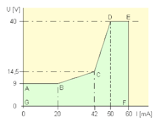
Fig. 1 The voltage on the raised phone would, depending on the passing stream should be in the area indicated by the letters A to G
The most important part of the phone is a colloquial circuit. The call is transmitted over the line modulation current that flows through the line. The current is modulated on the side panel (
VoIPGateway), which transfers the call to the user, and in the device, which is transmitted from the user. The speech circuit is a hybrid circuit that suppresses the signal from the microphone in the earpiece. The hybrid circuit is on the opposite side (PBX,
VoIP gateway). The hybrid circuit is usually some sort of bridge, and therefore it is necessary to impedance phone and VoIP gateway (or exchange) have been adapted. It is important especially for
VoIP devices, where the influence of digitization and transmission of data over the Internet arises signal delay in the order of tens of milliseconds. Mismatch, especially on the
VoIP gateway, there is a very annoying echo.
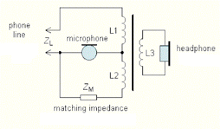
Fig. 2 Colloquial hybrid transformer circuit. If L1 and L2 have the same number of threads and balancing impedance ZM is equal to the line impedance ZL, the microphone signal in the handset suppressed
Another important part of the circuit for dialing. All modern devices support tone dialing. Ringing circuit to alert the user to an incoming call. Acoustic (bell) or optical signals indicates the presence of ringing voltage on the line. Hook switch is a switch that turns on the circuit colloquial answer the phone.
Specifications
Telephone impedance: | aprox. 600 Ohm. |
Recomended line impedance: | real. 600 Ohm. |
Operating (off-hook) current: | 20 mA
(10 to 40 mA.) |
Operating voltage: | aprox. 7 V @ 20 mA. |
| Dialing: | DTMF |
"In-use" indication: | 3 to 15 V/ aprox. 1 mA |
On-hook current: | aprox. 0,01 mA @ 50 V |
Phone Circuit Schematic
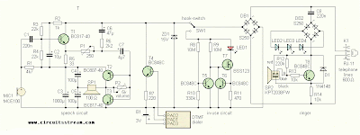
Fig 3rd Telephone unit schematic
Connection phone in Figure 3 Colloquial circuit with transistors T1 to T3 is connected via a hook switch and bridge DB1 to the telephone line . Diode bridge ensures that electronic circuits are supplied with the correct polarity. If the hook switch is closed, current passes through the transistor T1 lines , which is used as microphone amplifier and transistors T2 and T3 , which amplifies the signal to the receiver. Headphone amplifier operates in class A. The amplitude of the output voltage at the collector of the transistor is about 1 V, which for the purpose of completely sufficient . Headphones or speakers can be used with an impedance of 8 ohms , the amplifier but works better (has lower distortion) with higher impedance load . Trimmer P2 can adjust the gain as needed.
The amplifier is continuously drop of about 1.3 V, the sum of the voltage UBE transistors T2 and T3 and is only slightly dependent on the flowing current. This voltage across the resistor R1 is powered electret microphone . The signal from the microphone passes through C1 to the base of transistor T1 . It amplifies the signal level required to excite the line. Originally, the microphone amplifier much more difficult . But he had unnecessarily high gain and output impedance inappropriate . This simple connection works better . Working point T1 is set resistors R2 to R4 . The microphone amplifier there is a voltage drop of about 3.5 V , the voltage drop can be under current amplification T1 changed 3 to 4 V. Resistor R5 introduced at this stage, a negative feedback regulating the amplification and decreasing distortion. Balancing circuit C6, R6 and P1 suppresses the signal from the microphone in headphone amplifier .
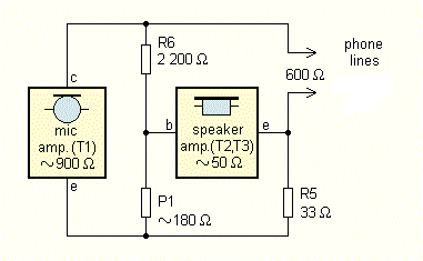
The signal from the microphone is on the collector of T1 opposite phase than the emitter , but the amplitude of the signal at the collector is much greater. Potentiometer P1 can set a condition where the signals from the collector and emitter of the capacitor C7 T1 readings and audio from the microphone in the handset is suppressed. Simplified diagram balancing the bridge is in Figure 4 The setting is very dependent on the impedance of the line. Because
VoIP gateway creates a link with the active resistance of 600 ohm and short supply does not create a significant reactive component , the setting is simple and very effective. The signal coming from the gateway or PBX is the collector and emitter of T1 phase balancing circuit and is therefore not suppressed.
Fig. 4th Simplified wiring hybrid (balancing) circuit in the phone
In order to suppress its signal worked well on the
VoIP gateway, you need the phone to be defined impedance close to the impedance of the gate, ie 600 ohm. The output impedance of the collector T1 for AC signals, large, almost current source. Impedance of the phone for voice signals are essentially a parallel combination of R6, R1 and about one order larger impedance collector T1. Rectifier bridge through which the signal passes, it will affect the impedance to a minimum.
Fig 5 Dialer circuit arrangement
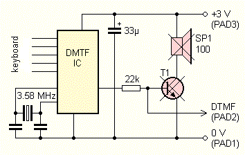
For DTMF I did not find any suitable integrated circuit , and generate DTMF signal discrete oscillators would be difficult and impractical . Finally, I modified the DTMF phone dialer . Dialer is a small box with buttons and speaker , generating tones when you press the button corresponding to the relevant figures. It is used for remote telephone answering and for the selective choice of the civil radio stations . The dialer (Fig. 5 ), the signal goes from the integrated circuit via the 22k resistor on the transistor, which drives a small speaker . Transistor speaker and I vymontoval a DTMF signal is connected to the transistor T4 on the phone. After pressing the button, the IO output voltage appears about 1 V with superimposed DTMF signal . Connect the telephone line is very simple, just enough transistor T4 and resistor R7. The change in resistance R7 can adjust the intensity of tone . Speaker of the phone dialer I used it as a handset . Dialer , according to the type of memory to 11 or 13 numbers , but unfortunately it lacks useful the " Redial" to repeat the last number called. I could not deal with power dialer from the phone line , so your phone is a small battery , which is likely to last for many years. The battery has an advantage in that it forgets the stored phone numbers if you disconnect it from the line.
Also, the ringing circuit I did not get special IO . That's why I like bell oscillator is used samovybuzujícím a piezoelectric transducer . The oscillator is fed stream that passes through the ringer capacitor C8 , bridges DB2 , LED2 to LED4 and resistor R14 . The oscillator is operated only in one half , the sound is more significant . In the other half cycle current through diode D1 . The bell must have a dead zone . That there is provided connecting the LED. Ringing voltage amplitude must have at least 10 V to Buzzer began publishing a sound. The phone I used a blue LED with high luminance. These intensely lit even at current several milliamps , which is ringing flow. LED also serves as a visual alarm bell , which could be useful in noisy environments .
The last telephone circuits are busy lamp . Phone I was seeking a second phone in parallel connected to the device at the other end of the apartment . When the phone is " suspended " , the hook switch is switched to the circuit with transistors T5 and T7 . If all telephones on the line hung on the line voltage of 50 to 60 V. The transistor T5 is opened, closed, and T7 LED1 off. The circuit is taken from the line is very little current through resistors R8 and R9 . Shrinks if the line voltage is below 15 V, T5 is closed , opens T7 and LED1 lights up. Transistor T6 T7 gate bias control by the loss of the R11 so that LED1 is energized about 1 mA , which is quite sufficient for display . In the voltage range of 3-15 V line lights LED1 virtually the same. BSS123 transistor has a maximum voltage UDS only 100 V. If the ringtone is this voltage is exceeded. In my phone's built higher voltage transistor has lasted several months . If you're worried about him , you can type BS108 with UDSmax 200 V, but it is not in SMD . The "in use" circuit not be planted, if you indicate you do not need , or can be used alone for another phone .
Mechanical DesignWidth of the printed circuit board was designed dimensions dialer , then the length of a "reasonable " distance between the microphone and earpiece. Although the board is a lot of space , most of SMD components . They take up less space and is easier mounting plate is not so much tinkering . Figure motive circuit and layout of components , following table .

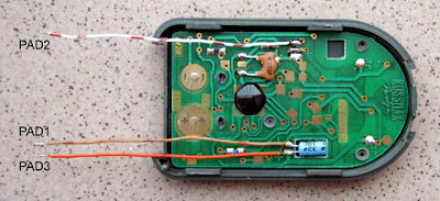
Before you assemble components, prepare the first dialer and attach it to desce.Z dialer remove the battery and remove the hinged cover. Dialer carefully "crack". It should go fairly easily if you start in the corner, to which is attached a chain. Odpájíme the speaker wires from the board dialer and speaker carefully shucks from the bottom of the box. The board dialer vypájíme more transistor in TO92. The board dialer solder short wires to negative (Pad1) and positive (PAD3) terminal electrolytic capacitor and terminal for transistor-based vypájeného (PAD2). Editing is perhaps evident from Figure 9 photos The lower part of the housing dialer yet only tentatively secured to the plate phone plastic rivets (Fig. 10). We remove the box and the board will be filled by phone components.
Fig. 6th Editing dialer and connection terminals
Phone was originally in a transparent plastic box, which was inside the LED backlight. Its production, however, I not successful, so I made a wooden box. To her I used plywood manufacture of soft wood, obtained from the fruit of hazel. That will free devoted almost everyone greengrocer. From one high hazels get material for a few boxes. Plywood is easily machined and well bonded dispersion adhesive. I eventually recut the box, namořil and přelakoval polyurethane varnish.
Fig. 7th Mounting boxes dialer
With the change in boxes I had to adjust some components on the board. LEDs were originally all SMD. Finally, there were only SMD LED 2. But it is not visible from the outside, and therefore does not need much light. You can replace the zener diode (3-12 V) or short-circuit, but it increases the sensitivity of the ringing circuit. Other LED in case of 3 mm diameter. It turns out that it is better to use LED with high luminous than type 2 mA of current, because the small stream shines more. Also switch SW1 on the phone "lifting", I moved to the side boards. Deferred phone is on the table laid down the keyboard. LED on the back because they are easy to see and switch is when you pick up the phone available with one touch. Of the joints it can not be soldered to the board just because they do not get tipped soldering iron to solder pad. On the solder contacts because I rozklepl small rivets, which I soldered joints by.
I then links to the rivets inserted the switch and soldered it from the opposite side of the board. Between the switch and the plate I put a piece of insulating paper. The switch can also be placed at any other suitable location in the box and board interconnect wires. Switches P-B143 of the newer series ("silver") are not too good and We turn the lever sometimes lose contact. To fix it so that "packs" pertinax holding plate with pins a little more same hopper. The defect had all the pieces that I had at home. Dimensionally the same switch, but painted black were fine.
Fig. 8th The top side of the printed circuit board
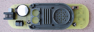
The power dialer instead of the original articles I used lithium batteries. Do you solder boards phone as housing purchased as the GM and housing that vypájíte of defective motherboards PC that has otherwise placed pins. Piezoelectric transducer is bolted small screws through the PCB to the bottom of the box dialer.
On the microphone I slid the piece of tubing so that the tubing fit snugly inside the box. Thus reducing the acoustic coupling between the earpiece and microphone inside the device.
Fig. 9th The underside of the plate and box
Fig. 10th The back of the phone with LED switch and a hole for the bell
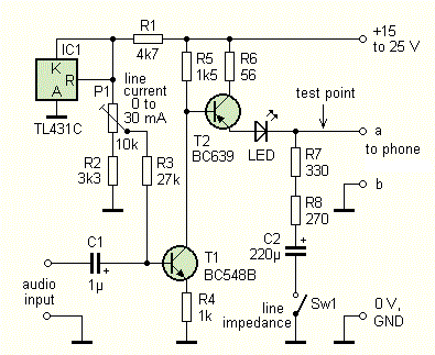
AnimationPhone use in conjunction with the gateway Linksys Sipura SP2100. In the firewall settings to make sure that in menu / admin / voice / advanced tab you have set up Regional impedance lines FXS Port Impedance: 600 Phone can revive a product as shown in Figure 14 (SW1 closed). You can test with a different phone when line current, measure the voltage on the line and estimate the impedance of the phone - AC voltage test point should be after the switch opens twice. The trimmer P2 dial to maximum resistance (max volume). To attach the microphone sound source (eg mp3 player headphones) and adjust the trimmer P1 so that the sound from the microphone not hear the telephone handset. Try tone. Ringing circuit you can try connecting the phone via a suspended resistor 1 kOhm to AC voltage 24-50 V.
Fig. 11th test preparation
ConclusionThe phone is in operation for several months and yet it was conceived as a second auxiliary telephone is often used. I have tested it successfully on the public switched telephone network (PSTN), but because I'm not sure whether it meets all required standards, there should not be connected. PSTN to
VoIP gateway over a larger voltage when hanging up a more current when the phone is picked up.
List of components
| R1 | 4,7 kOhm, SMD 1206 |
| R2 | 1 kOhm, SMD 1206 |
| R3, R4 | 22 kOhm, SMD 1206 |
| R5 | 33 Ohm, SMD 1206 |
| R6 | 2,2 kOhm, SMD 1206 |
| R7 | 220 Ohm, SMD 1206 |
| R8, R9 | 10 MOhm, SMD 1206 |
| R10 | 330 kOhm, SMD 1206 |
| R11 | 470 Ohm, SMD 1206 |
| R12 | 220 kOhm, SMD 1206 |
| R13, R14 | 10 kOhm, SMD 1206 |
| P1 | 250 Ohm, trimr PT6V (Piher) |
| P2 | 5 kOhm, trimr PT6V (Piher) |
| |
| C1 | 220 nF, SMD 1206 |
| C2 | 10 mikroF/16 V, tantalum., SMD B |
| C3 | 1000 mikroF/6,3 V, electrolytic |
| C4, C5 | 100 mikroF/6,3 V, tantalum, SMD D |
| C6 | 47 mikroF/16 V, tantalum., SMD D |
| C7 | 4,7 mikroF/10 V, tantalum, SMD A |
| C8 | 220 nF/250 V, foil MKT RM5 |
| |
| PCB board bcs59 |
| D1 | 1N4148SMD, SOD80 |
| DB1, DB2 | S250,mini DIP bridge |
| ZD1 | BZV55C15SMD, Zener. diode 15 V SOD80 |
| T1, T3 | BC817-40, SOT-23 |
| T2 | BC807-40, SOT-23 |
| T4 až T6, T8 | BC848C, SOT-23 |
| T7 | BSS123, SOT-23 (BS108, TO92) |
| |
| LED1 | high intensity 3 mm red LED (it's better than 2 mA LED) |
| LED2 | any 3 mm SMD LED or Zener diode 3 to 12 V |
| LED3, LED4 | high intensity 3 mm blue LED (it's better than 2 mA LED) |
| |
| MIC1 | elektret. mikrofon MCE100 |
| SP1 | tiny speaker or headphone 100 Ohm (8 to 100 Ohm),
removed from dialer |
| B1 | CR2032 battery and holder |
| SW1 | P-B143, SPST switch |
| K1 | slim RJ11 plug WEBP 6-4 LP |
| SP2 | piezo KPT2038FW |
| dialer | dialer DTMF 13 or 11
|


